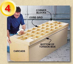
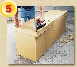
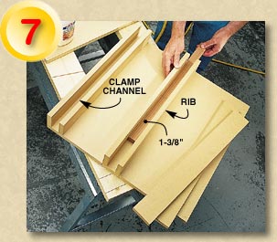
THE TORSION BOX

The torsion box is designed to resist twisting. It consists of a web core made up of MDF strips notched for easy assembly (Fig. A). To ensure each piece is notched the same, gang cut the notches on the tablesaw (Photo 3). Glue and screw the sides (T2) and ends (T3) first to create a frame. Assemble the core grid (T4 and T5) inside the frame along with the corner blocks (T6) (Photo 4). Place the torsion top (T1) over the core grid and tack it in place. Be sure all the edges are flush (Photo 5). Then weight the top for clamping pressure (Photo 6). Once the glue has set, remove the weights, flip over the torsion box assembly and glue on the bottom (T1).

With the torsion box complete, add the casters and the levelers (T7). The carcass is then screwed down onto the torsion box (Fig. A).

BUILDING THE BOXES
There are four boxes that complete the tool stand. Two of the boxes are permanently fixed to the top to form the tool well (Fig. A). The other two, the downdraft table (Fig. C) and the router table box (Fig. D) are used as inserts between the fixed end boxes. Assemble the fixed boxes with glue and screws (Photo 7). Add plastic laminate for a durable top. Or, skip this step and simply treat the surface with a couple coats of polyurethane (it’s a great way to use up that old can that’s been opened a few too many times).

Cut the 3/8-in. T-slots in the top with a dado blade on your tablesaw. Attach the fixed boxes to the top and be sure to keep all the edges flush (Fig. A).

DOWNDRAFT
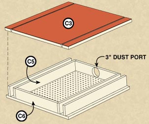
 BOX
Assemble the downdraft box from the inside out (Fig. C). First, glue and screw the two inside ribs (C5) to the filler pieces (C6) to create the interior structure. Then attach the bottom. Use the spacer stick to attach the outside ribs. Note: The sides of the insert boxes are inset 1-in. so they will clear the chop saw fence stop blocks (C8).

Drill a 3-in. hole into the center of one filler piece for a dust collector fitting. Perf-board makes a great template for drilling the 1/4-in. holes in the top. Use a countersink to widen the opening of each hole.

ROUTER
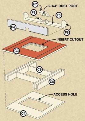
 TABLE BOX
Assemble the router table box. Note: The bottom of the router table box is cut 2-in. narrower than the top, making it flush with the outside ribs (Fig. D). This allows the router table to be lifted in and out of the well with the router attached.

The router is mounted onto a table insert that sits flush to the top. This allows you to lift the entire router out of the table for changing bits. Make two 8 in. by 16-in. access holes, one in the bottom of the router table and the other in the top of the carcass. These holes allow room for a pair of hands to adjust the router.

TOOL BASES
The chop saw is screwed to a piece of 1/2-in. plywood sized to fit into the well. To make positioning of the saw and the auxiliary fences easier, line up the front edge of the saw base with the front edge of the tool stand well. Behind the saw, drill two 1/4-in. holes through the base and the carcass. Mount T-nuts to the underside of the carcass top (Fig. A) and secure the saw with T-handle knobs. Clamp a straightedge to your saw’s fence and position the chop saw fences against it. Nail the stop blocks to the fixed boxes. The planer base is made from a piece of 3/4-in. plywood. The two 1-5/16 in. by 24-in. supports bring the planer bed up to the same height as the fixed end boxes. Your planer bed may vary, so size the supports accordingly.

That’s it. You’re done! Now your shop will seem two sizes larger without moving a single wall!


Spread glue on all the edges of the torsion box core. The torsion box can only be as flat as the surface on which it is built. Build it on the carcass laid on its back (which will be dead flat). Lay the bottom of the torsion box on the carcass and assemble the core grid. The corner blocks are attachment points for the casters.


Tack the top onto the core grid. Be sure all the edges are flush.


Clamp the top onto the grid with weights and extra sheet stock. The extra sheet stock helps distribute the weight of the blocks evenly.


Use a 1-3/8 in. by 1 in. by 24-in. spacer stick to help lay out the ribs on all the boxes. Use the 1-3/8-in. side to space the double ribs on all the boxes and the 1-in. side for the overhang on the two inserts (Figs. C and D).


Ultimate Tool Stand - Exploded View & Electrical Connections
Building the Ultimate Tool Stand
- Building the Ultimate Tool Stand (continued) - 
Special Features - Special Features (continued)
Cutting List & Shopping List